Versatility in the CEREC® World Today

Sponsored by Ivoclar
I had the amazing opportunity to witness eight smile transitions in a single day. Eight unique, life changing moments for both the doctors and the patients. While I wish I could share in detail all of the stories that were entrusted to us from the patients, I am excited to share a few of the cases from novice CEREC users to experienced users, and the wide variety of treatment options that were possible through today's technology and IPS e.max CAD. These cases were not done by my hands, but I could not be prouder of the work that was done. As a long-time user of Ivoclar Vivadent products, I was excited to partner with them and I appreciate the amazing support in donating the materials for this cause. The cases that were done involved multiple types of restorations, all IPS e.max, from crowns, to bridges, to implants as e.max offered incredible versatility in these cases while also demonstrating the strength and beauty that we were looking for.
Cathleen
When I first met Cathleen and asked her what a new smile would mean to her, she told me that she was looking for confidence to smile again and not be embarrassed. She has had an incredible life journey and a new smile would represent the person she has become, not the person she once was.
Cathleen had veneers placed on her upper and lower anteriors 20 years ago which started to break and fall off (Figure 1). She was not in a position to get them fixed and the exposed dentin started to cause pain. She presented with edentulous areas on the upper right and lower left, leaving her with little chewing surface in the posterior regions. The treatment plan is to establish her smile line first, and then she will be receiving implants in the posterior and the remainder of necessary treatment.

Figure 1. Before retracted photo.
A digital wax up was completed for the full mouth, but for the purposes of this phase of treatment, fabricating crowns for #6-11, we also had a digital wax up for only the upper anterior teeth #6-11 done so that the wax-up and the remaining teeth would stitch together in Biogeneric Copy (Figure 2). With the software updates today, using the Biogeneric Copy design mode is easier than ever before, allowing for efficiency in these large cases (Figure 3). The six crowns were milled out of IPS e.max, shade A2 MT, contoured, glazed and stained. The hand contouring is what can really set a case like this apart, knowing the anatomy and defining the line angles a touch more than what the mill can do (Figure 4). The stain and glaze system used was IPS e.max CAD Crystall. Fluo glaze was utilized, and the stains were shade 1 for gingival warmth, shade I 2 for translucency and shade Creme for the framing (Figure 5).

Figure 2. Digital wax up provided from a lab and printed from SprintRay Pro.

Figure 3. BioGeneric copy "stitch" of design and wax up.

Figure 4. Anatomy of anterior teeth for contouring post mill.

Figure 5. Stain pattern used to give natural appearance to restorations.
After the crowns were fired, the teeth were isolated using an Optragate and bonded in. To prepare the restorations, Monobond Etch and Prime was scrubbed into the intaglio surface for 20 sec, let rest for 40 sec and then rinsed. This one-step system to prepare the restorations is just one more advancement for simplicity and efficiency in chairside cases. One of my favorite tools for rinsing crowns chairside is the Etch-Ease Holding System as shown in Figure 6. This is fantastic for preventing restorations from getting sucked into the high vac when removing any surface cleaner from crowns or veneers. The teeth were prepared by scrubbing in the Adhese Universal Vivapen bond for 20 sec, air drying until there is no movement of bond, light cured for 10 seconds and then bonded on the crowns. Tack cure for 3 seconds each side, remove excess, and fully cure.

Figure 6. Etch-Ease Holding System for removing surface cleaners to intaglio surface of crowns.
There is so much magic in cases like this not only for the patient with their new smile, but for the doctor as well, with the knowledge that she created that smile with her own hands. This case was done by Dr. Kirsten Andrews and when she delivered this case, there was not a dry eye in the room (Figure 7). I recently saw Cathleen for a post op visit and to prepare her for her next section of treatment and I am proud to say that she just can’t stop smiling (Figure 8).

Figure 6. Dr. Kirsten Andrews post delivery of the crowns.

Figure 8. Before and after smile photo.
Felicia
Nothing breaks my heart more than when a young patient covers their mouth when they speak because they are so embarrassed by their smile. Felicia presented with decay on every tooth, and on almost every surface of every tooth (Figure 9). She hated her smile, and it had gotten to the point where she was just overwhelmed by the amount of appointments and the cost. Although I was really excited about the change and impact we could do for this case, when I first saw her, I knew a huge challenge would be her bite. With that much overclosure and “tight bite”, it is evident that she has a restricted envelope of function which could be a source of the fractured teeth. Personally, I think “tight bites” are one of the largest challenges we face in reconstruction.

Figure 9. Initial before smile photo with heavy decay and stain present on every tooth.
The teeth were prepped but the patient was warned of the potential need for root canal therapy due to rotation and decay. A digital wax up was also done as a map and guide for the case. The doctor practiced prepping the case on a 3D model to ensure enough reduction would be done (Figure 10). We also discussed reducing the lowers to help create more space. Cases like this are perfect for use of the articulator function in the chairside software to minimize the interferences and potential problems. The articulation function can be found and turned on in the Administration screen as seen in Figure 11. I do not normally check the box to “Use Articulation for initial proposal” because it can load the system down too much. After I finish the design, I do check the Occlusal Compass to look for interferences and modify the design as necessary (Figure 12). This is a fantastic tool to minimize post-operative complications and does not take a lot of extra time.

Figure 10. 3D wax up, practice preps, and original 3D model printed on SprintRay Pro.

Figure 11. Administration screen of how to set up articulation feature.

Figure 12. Articulator function within chairside software.
The crowns milled were e.max A2 MT and was characterized minimally with IPS CAD Crystall e.max stains and Fluo glaze. I2 was used for the translucency and Crème for the framing of that translucency (Figure 13). The restorations were bonded as described in the case above using Variolink Esthetic resin cement. This case was beautifully done by Dr. Jacquie Angell and her team. As you can see in Figure 14, the patient was incredibly excited and grateful about her new smile and looking forward the rest of her treatment. What an incredible transformation and service for this patient (Figure 15).

Figure 13. Minimal stain and glaze pattern with natural effect of e.max.

Figure 14. Initial reaction of the reveal of her new smile.

Figure 15. After smile photos of e.max crowns #6-11, shade A2 MT.
Tina
Tina presented with edentulous areas in the posteriors in all quadrants and a large abscess on tooth #10. The bone defect from the infection was so large that it made the possibility for an implant in that site difficult. The tooth was extracted and grafted four months prior to her anterior teeth being restored (Figure 16). Teeth #s 6, 7, 8, 9 and 11 all had recurrent decay present with large fillings. Tina wanted the confidence to smile again, and we began her treatment plan with the upper anterior restorations to start this process. The plan was for single unit restorations on #s 6, 7, 8, and a 3-unit bridge from #9-11. A digital wax up was completed with only the anterior upper 6 mocked up so that the models would stitch. Originally when we discussed what the patient was looking for with her new smile, she had mentioned that she wanted her existing diastema closed, but when it came time to the prep day, she had changed her mind wanting to keep that character trait (Figure 17). What I love about this case in particular is that the dentist who restored the case did not have much experience with CEREC. However, because the new software and hardware is so user-friendly, she had no problem navigating this case and executed it beautifully.

Figure 16. Initial retracted photo.

Figure 17. 3D printed models from the SprintRay Pro of original scan, preps and digital wax up.
The design method for this case was Biogeneric Copy (Figure 18), but as mentioned before, the doctor had to open up the diastema. This can be done by using the group function, selecting #8 and #9, and then selecting the anatomical 2D tool to evenly open the gap between the centrals (Figure 19). The suggested connector size for an e.max bridge is 12 mm squared which was achieved by using the Anatomical Connector design and then extending the connector on the lingual surface as much as the bite would allow. The crowns and bridge were milled with e.max blocks, shade A2 LT, as e.max bridge blocks are only available in LT. The crowns and bridge were contoured by hand and then characterized using IPS e.max CAD crystal stains and glaze. The connectors of the bridge were distinguished using shade 1 to give the illusion of slight staining and separation of the teeth. The stain, shade Creme, was used for slight craze lines giving the teeth a natural appearance appropriate for the age of the patient. The translucency was highlighted by using a mixture of shades I1 and I2 and then that was framed with the shade white stain at the incisal edges and 1/3 of the way down on the mesial and distal marginal ridges as shown in Figure 20. After the ideal characterization was achieved, an Optragate was placed, and the restorations were bonded in using Variolink Esthetic resin cement.

Figure 18. Original BioCopy design from digital wax up with diastema closed.

Figure 19. Design using Shape > Anatomical 2D tool after grouping #8 and 9 for symmetrical modification of the centrals.

Figure 20. Staining and glazing pattern using IPS e.max CAD stains and Fluo Glaze.
When this case was delivered, I am not sure who was truly more excited, Tina or Dr. Michelle Falbo, which is who restored this gorgeous case (Figure 21). Dr. Falbo had limited experience with CAD/CAM in the past and was not truly convinced of the capabilities of the CEREC, especially with anterior restorations. This was not an easy case to begin with, having spacing discrepancies and mixing bridges and single unit crowns in the treatment, but she executed it beautifully and is now a true believer of CEREC and same day delivery. The patient was thrilled with her new smile and looking forward to the next steps of establishing her posterior occlusion with implants and single unit restorations.

Figure 21. Patients initial reaction to her new smile.

Figure 22. After retracted photo of same day delivery. E.max crowns #6, 7, and 8. E.max 3-unit bridge from #9-11, shade A2 LT.
Crystal
Crystal presented with uneven diastemas and spacing on her upper anterior teeth with an edentulous space for #11 (Figure 23). An implant was placed six months prior to this treatment phase and is ready to restore. She did not want to go through orthodontics, but she did want to fix the gaps in her teeth and get rid of the decay. The challenge is the uneven spacing right and left of the midline, and also the canted midline. This is a perfect case for a digital wax-up to provide more ideal proportions and allow the patient to see where the case can go (Figure 24).

Figure 23. Initial smile photo showing uneven diastemas from left to right side and edentulous space #11.

Figure 24. Digital wax up showing roadmap of possibilities
What I love about using e.max is the versatility of different types of restorations. The implant crown and the single unit restorations can all be done with one material, which gives a more natural result. What is great about CEREC is you can do multiple restoration types at once, meaning you can select crowns and the implant crown in the same file (Figure 25). The plan for imaging purposes is to prepare the restorations first, making sure the margins are clear, the preps are smooth, and the substructures are all similar to allow for a more natural appearance of multiple restorations in the smile (Figure 26). The next step is to remove the healing cap and image the prepped teeth in the Upper Jaw folder, and then place the ScanPost in for #11 and scan this into the ScanBody Upper folder. Scan the lower jaw and Buccal Bite as normal and start to design the case (Figure 27).

Figure 25. Administration page of multiple types of restorations at once.

Figure 26. Prepped teeth #6-10 prior to implant impression.

Figure 27. Acquisition screen of CEREC for cases with multiple types of restorations such as implants and crowns.
Due to the placement of the implant, there was not enough room to do a custom abutment and crown, so a screw-retained crown was the only option for same day delivery. The access hole was on the incisal facial edge which was not ideal. One way to fix this would be move all of the restorations more buccal which would move the access hole more lingual, but because of the existing spacing this also would have made the teeth larger which was not ideal (Figure 28). We compromised on the access hole being visible and honestly the patient was so grateful for her new smile, she didn’t even notice the access hole. Another option would have been to have a custom abutment fabricated outside of the CEREC workflow, but this was not within the realm of our capabilities for this day.

Figure 28. Occlusal screenshot of design with access hole of screw-retained crown on facial insical.
To minimize the illusion of wide teeth, youthful anatomy was designed into the wax up, meaning that the central lobe and mesial and distal depressions were distinct. The trick is not having it so prominent that the patients find it annoying but breaking up the light helps the teeth not look so wide (Figure 29). After the characterization was complete, the crowns were seated first using Variolink Esthetic and the implant crown was seated last. The TiBase was seated outside of the mouth by sandblasting the TiBase and priming the metal with Monobond Plus. The screw retained crown was prepared with Monobond Etch and Prime, rinsed and then Multilink Hybrid Abutment Opaque cement was used to bond the TiBase to the crown. It needs to sit for 7 minutes prior to seating it. The implant crown was torqued to the value given by the implant company.

Figure 29. After retracted photo with youthful anatomy.
The midline is straight, the diastemas are closed and the patient is so excited for her new smile. Dr. Katie Kennedy wanted the challenge of mixing an implant crown into the process of a smile design case and she did a magnificent job at creating the illusion of a more even smile with a natural looking result.
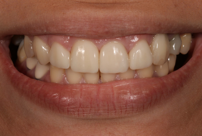
Figure 30. After smile photo of e.max crowns #6, 7, 8, 9, 10 and screw retained implant crown #11, shade A1 LT.
Conclusion
As dentists, we always strive to do ideal dentistry but sometimes there are real life situations that prevent it. I would have loved to see all of these cases go through orthodontics, make sure all of the decay is removed and restored and have every patient be on an ideal hygiene schedule, but these are patients who have life circumstances that prevent it. I am honored that these patients allowed us into their lives. They gave us the opportunity to take them one step closer to building the confidence to change their life situations, and that is what this is all about. We do have plans to deliver the rest of the needed treatment if they choose to let us but for now, I appreciate the dedication and time that these doctors gave and the impact they made by giving these women hope again. How fortunate are we, that we have the capabilities to do this chairside with IPS e.max and CEREC!
