CONE BEAM Article
Mastering 3D Digital Imaging: A New User’s Guide for Optimizing a Volume for Review
Dr. Steven Hernandez
CDOCS Faculty

Embarking on your journey in 3D digital imaging in dentistry is an exciting step. However, new users can sometimes encounter challenges with image quality. Have you ever noticed that when you first take an image, it appears stretched or compressed, or perhaps you’re missing the incisal edges of the maxillary or mandibular teeth? These common issues can be easily addressed.
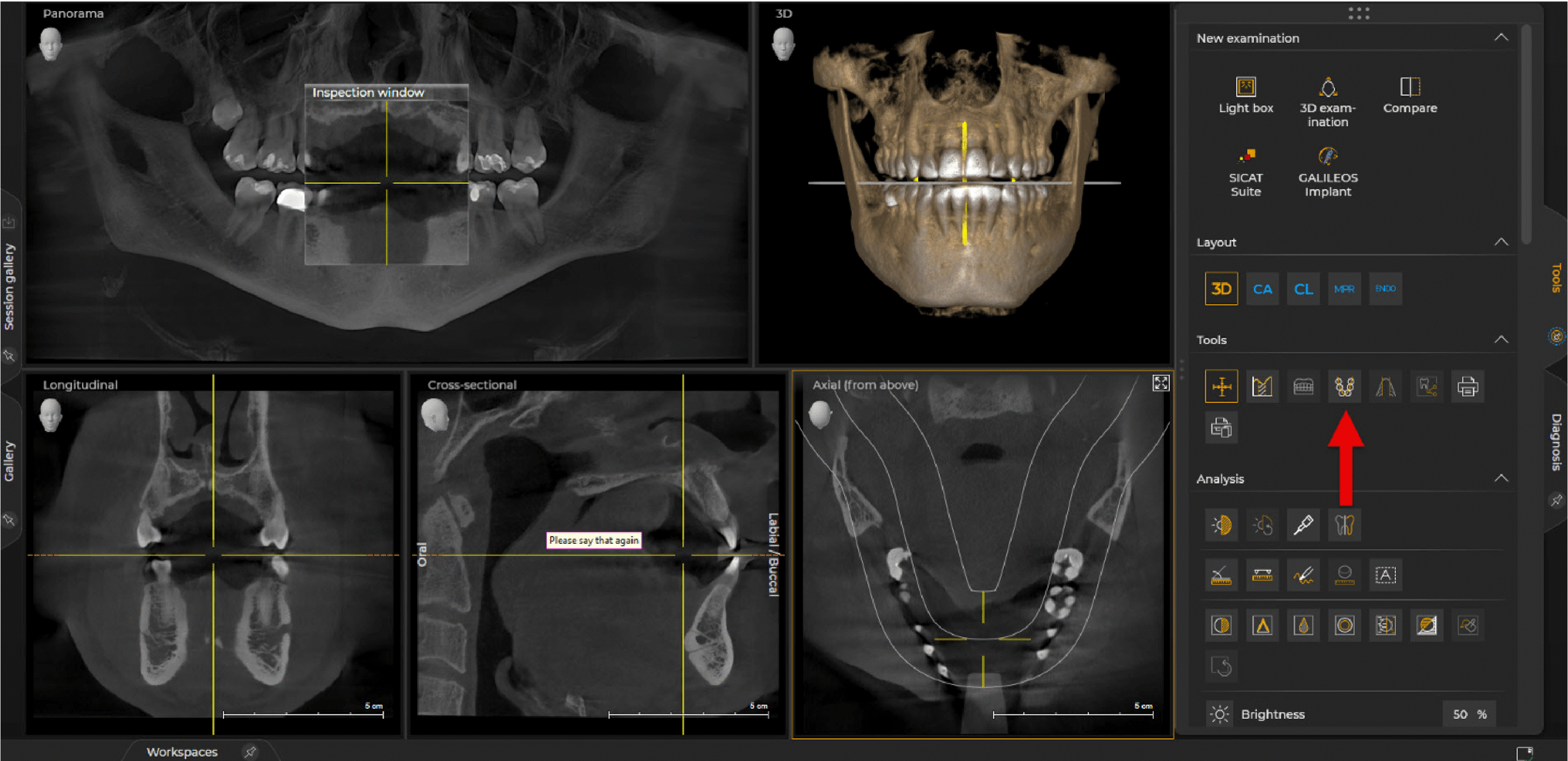
When a new image is taken, you’ll see the following five windows which is the default 3D layout.
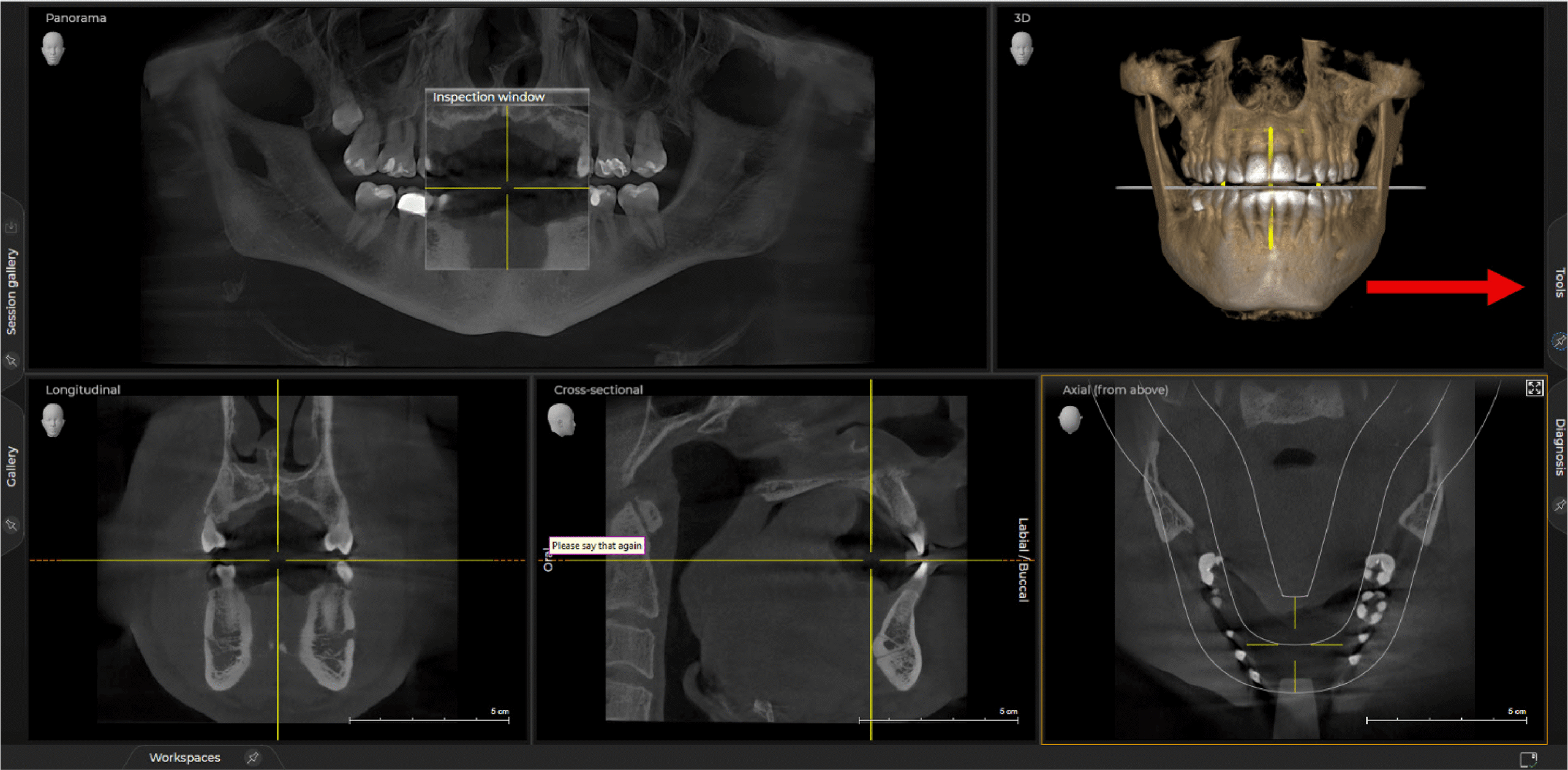
Before you navigate through the volume, the first step should be to adjust the 3D curve. In my office, this task falls to whomever takes the x-ray on the patient. To adjust the layout, look to the right of the screen. There you will see two tabs, Tools and Diagnosis. Select the Tools tab.
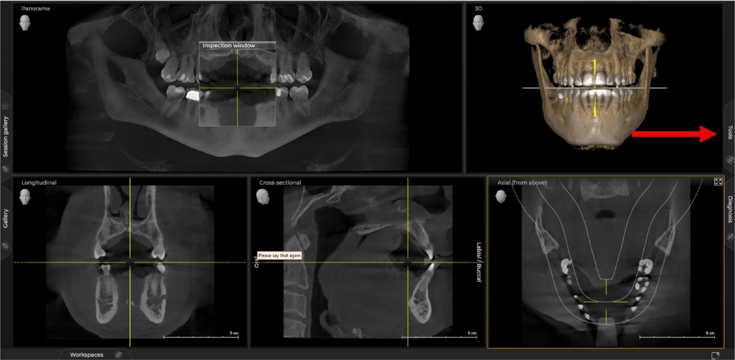
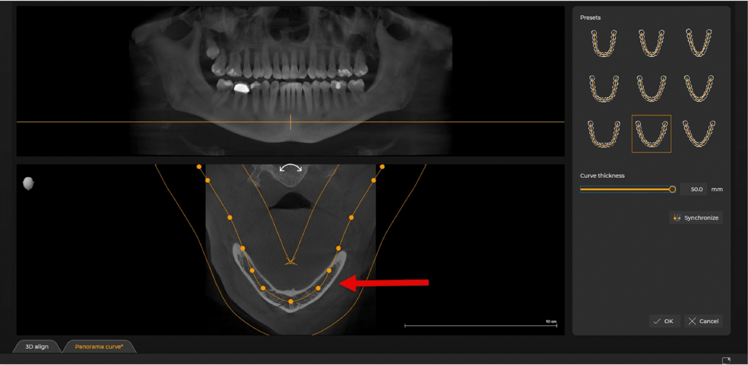
Now you will see various icons that can help you adjust the image, measure a distance within the software, draw on the screen, etc. The icon we are looking for is under Tools and appears to be a mandible designated by a single line in the shape of U with circles on top of it.
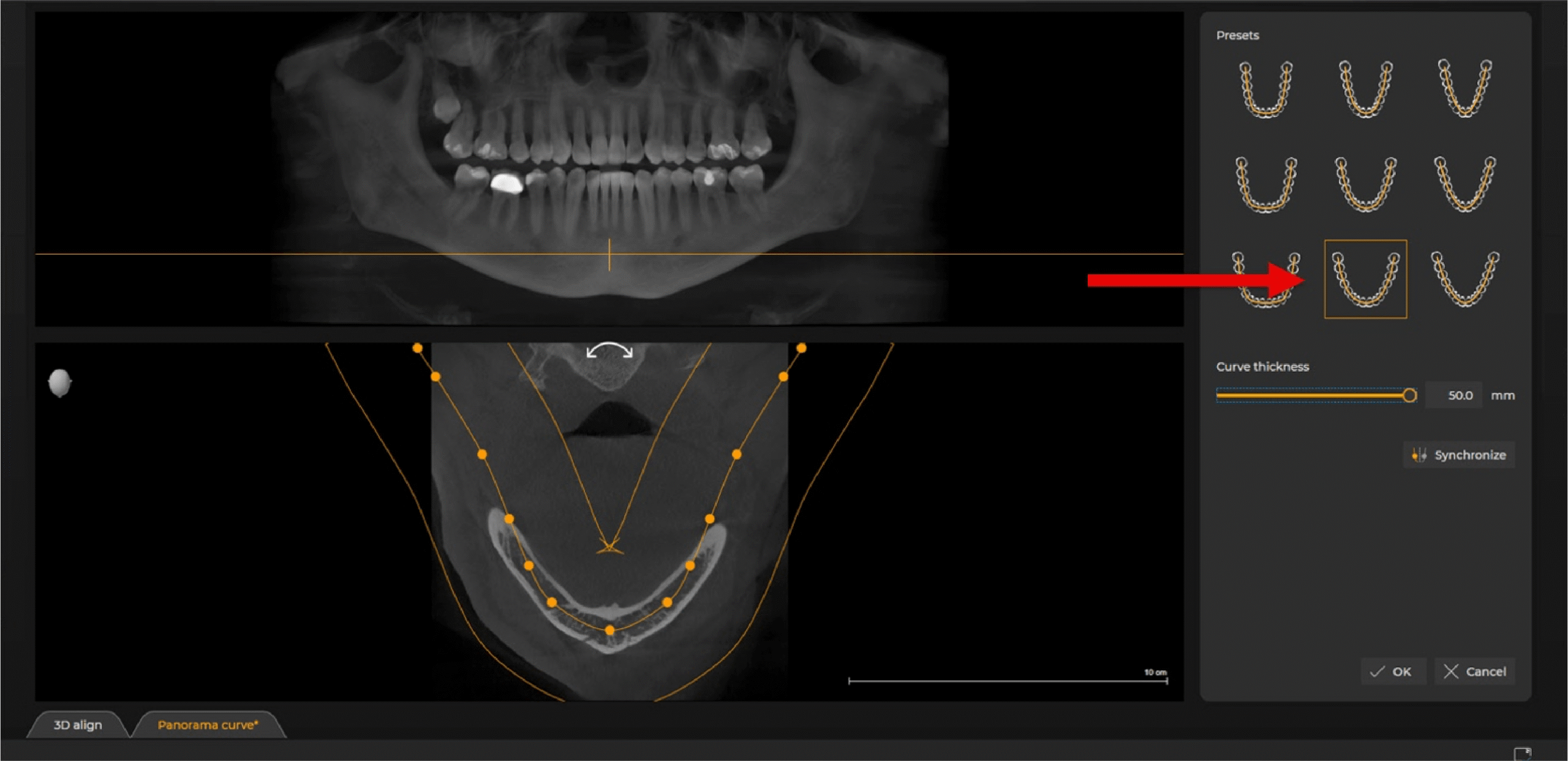
To optimize your viewing, begin by selecting the appropriate jaw preset, typically the bottom middle one.
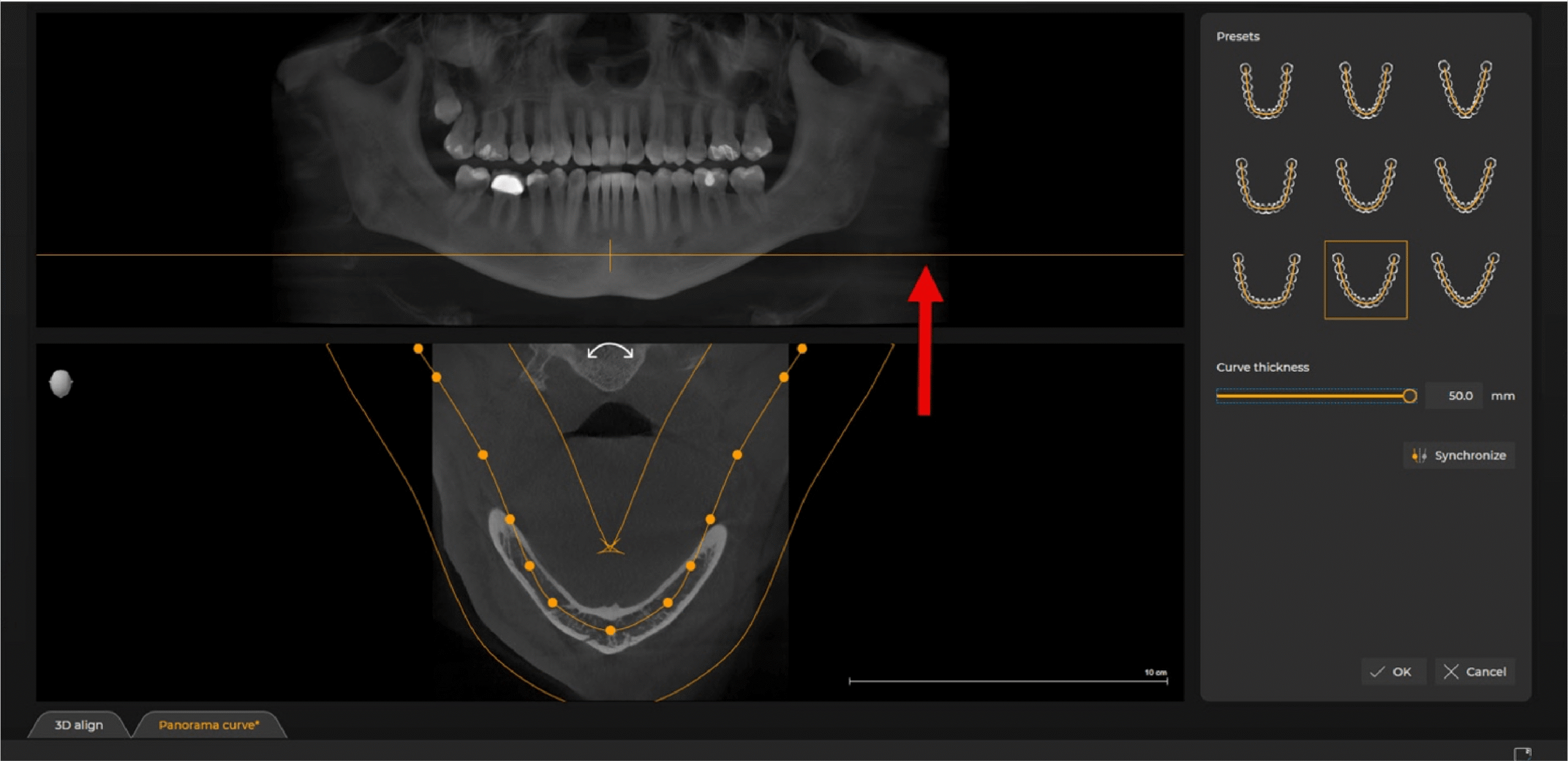
Next, adjust the curve thickness. The default setting is 30 mm. But maximizing it to 50 mm is crucial.
This step ensures that all radiographic data within the buccal and lingual borders is visible, preventing the common pitfalls mentioned earlier.
Next, pay attention to the orange line displayed in the top left of your reconstructed pan. Move this horizontal line down to the patient’s mandible, specifically positioning it where the mental foramen are.
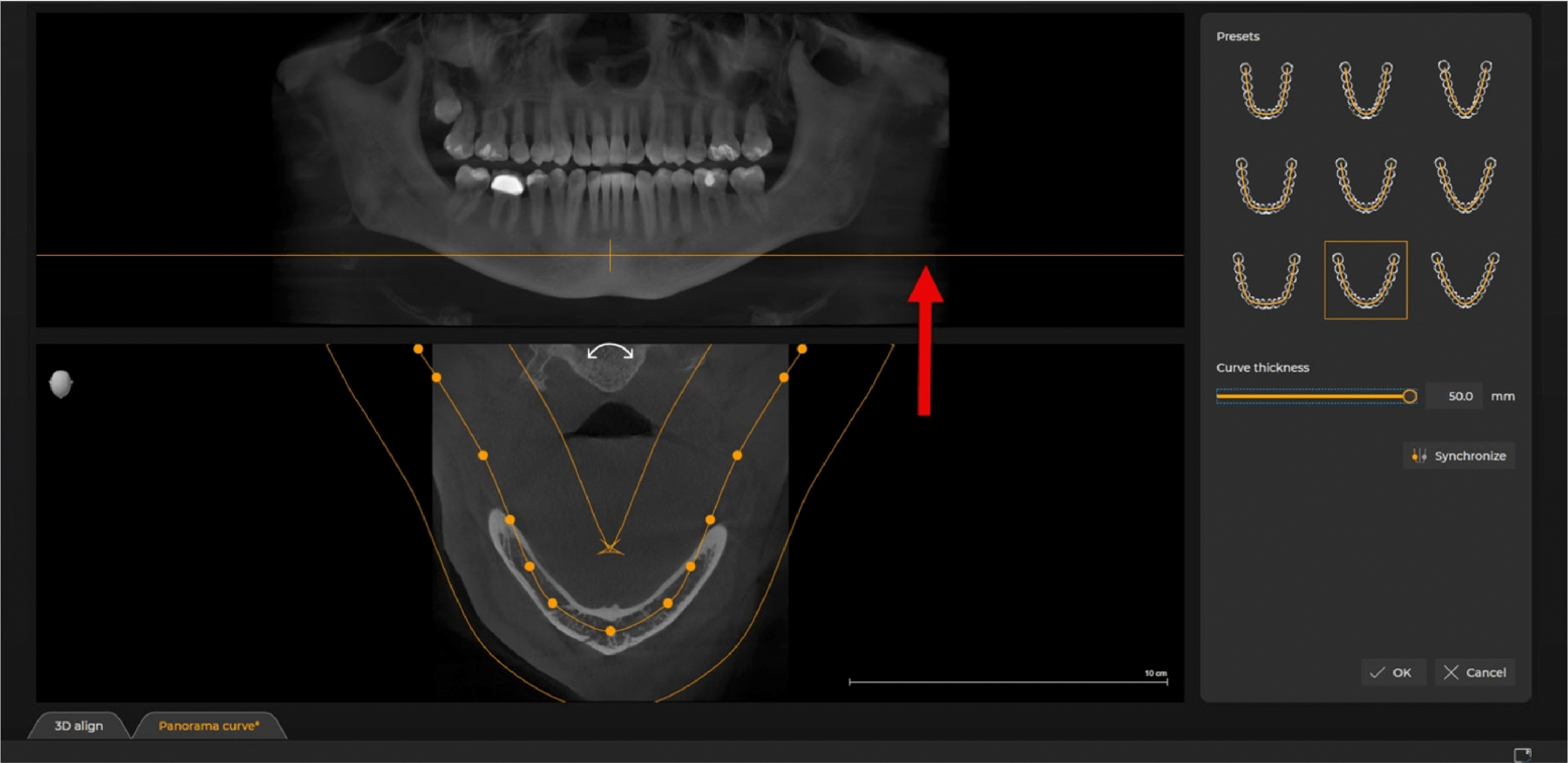
The reasoning behind this is to have radiographic data in the image below so that it’s easily visible and you’re able to center it within the curve thickness.
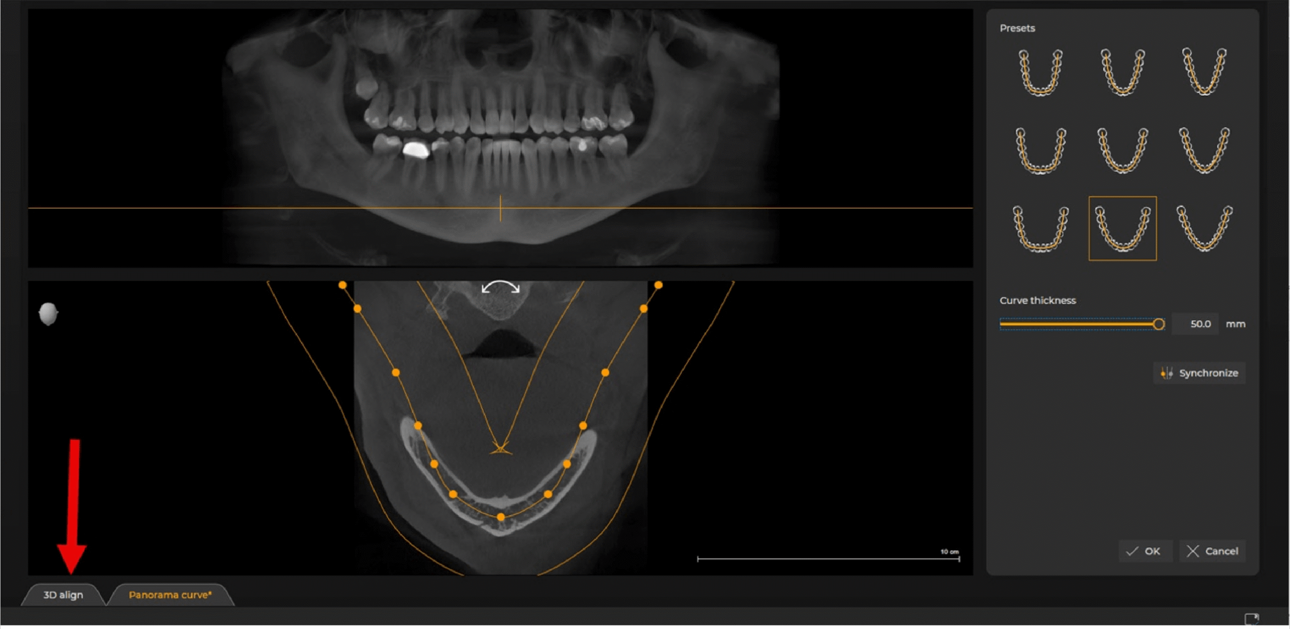
Lastly, you can also correct the volume where the patient was incorrectly positioned. Perhaps you have a new team member or a patient who has a physical limitation and can’t place her head upright and their jaw parallel with the floor. While this doesn’t happen often, here is how you correct it. In the same 3D layout screen, you will see a 3D aligned button in the very bottom left; select it.
Here, I’ve purposely manipulated the image to show you what a bad position would look like. In the top right, you’ll note that the patient’s head is tilted to their right, they are looking down, and not straight ahead. To correct this, use the three colored circles toward the bottom of the screen; red, green, and blue.
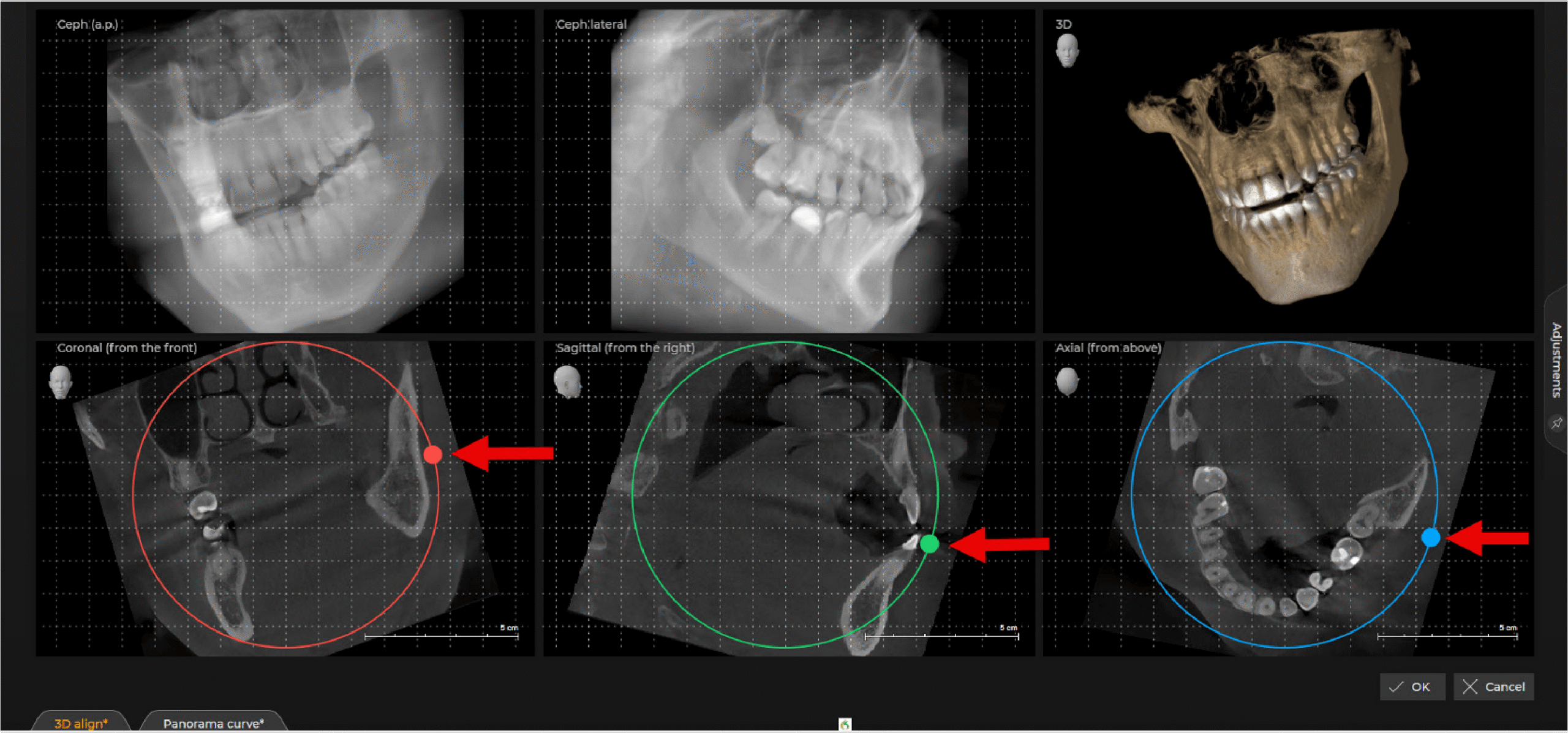
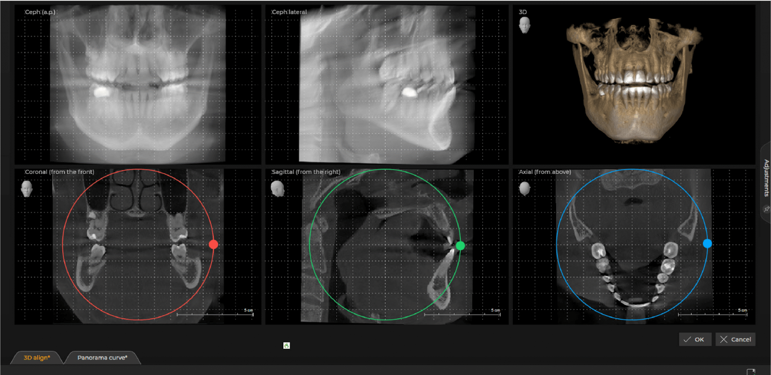
Place your cursor over one of the colored-in circles, left click and hold your mouse button, and move your mouse while looking at the 3D tad in the top right. The goal is to position the patient so their occlusal plane is parallel with the floor, not tilted to either side, and looking directly at you.





Conclusion
When finished, click OK and you are returned to the original 3D layout. These functions take mere seconds and only need to be done the first time the volume is opened on a patient. Once set, they are saved so this function doesn’t have to be done each time you open that volume.
Related CDOCS Hands-On Workshops
Implementing Cone Beam for Practical Utilization (CB110)
Get comfortable with cone beam technology through hands-on training in CBCT hardware operation, full volume review, and Sidexis and Sicat software suites, including introductions to CAD/CAM integration, airway analysis, and implant and endodontic applications to unlock your system’s full potential.

Maximizing Diagnostic Efficiency with Cone Beam (CB210)
Enhance your ability to systematically review CBCT volumes, identify and categorize radiographic abnormalities, and effectively collaborate with maxillofacial radiologists.