 Dan Butterman, D.D.S.
 There are multiple workflows for restoring implant supported bridges with CEREC. The CEREC Chairside software and TiBase workflow is a good option for restoring single implant crowns, but this workflow is much more labor intensive for restoring bridges. This is the typical CEREC TiBase workflow for implant bridges:
- Scan the retainer implants with a Dentsply Sirona ScanPost
- Design individual split restorations for each implant
- Mill only the abutments
- Bond each abutment to a TiBase
- Bring the patient back to insert the abutments and re-scan in the mouth
- Treat the abutments as teeth and design a conventional bridge
The Atlantis workflow allows for the retainer implants to be similarly scanned but using an Atlantis IO FLO ScanBody. The scans are sent via the Connect software to Dentsply Sirona Implants. On the prescription, the clinician can request to make the abutments parallel in order to have a passively fitting bridge. A core file is then returned to design and manufacture the bridge. This workflow involves less appointments and results in an excellent fitting bridge. These are the steps in the typical Atlantis workflow for implant bridges:
- Scan the retainer implants with an IO FLO and send via Connect to Atlantis (Dentsply Sirona Implants)
- Request parallel abutments and approve design
- Open core file, design, and manufacture a conventional bridge
- Seat abutments and bridge
This case involved a failing bridge from #18-21 (images 1 and 2). Both #18 and #21 were non-restorable. The patient had an Axeos CBCT Scan and an optical scan with CEREC 5.1.2 Chairside software. Teeth #19, 20, and 21 were virtually extracted from the model (image 3), and implants were planned in SICAT 2.0 software at positions #19 and #21 (Image 4). The restorative plan was to fabricate a three-unit bridge from #19 to #21. Two CEREC Guide 3 surgical guides were fabricated to ensure proper implant placement (image 5). The bridge was sectioned, leaving #18 in place to help support the surgical guides (image 6). Tooth #21 was extracted, and implants were placed at sites #19 and #21 (image 7 and 8). Tooth #18 was then extracted. IO FLO ScanBodies were placed and imaging was done to fabricate custom healing abutments for implants #19 and #21 (image 9). The stock healing abutments were screwed into the implants, and sutures were placed (image 10). The IO FLO scan was sent to Dentsply Sirona Implants. The prescription for the custom healing abutments was submitted on the Atlantis Weborder site, and a design was ready to approve within a few hours (image 11). The custom healing abutments arrived two days later. When the patient returned for the one-week post op, the stock healing abutments were replaced with the custom healing abutments.
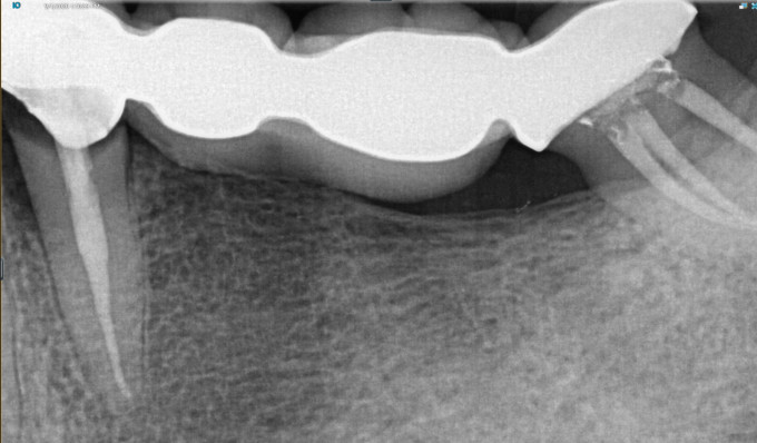
Image 1. Pre-op radiograph of failing bridge #18-21
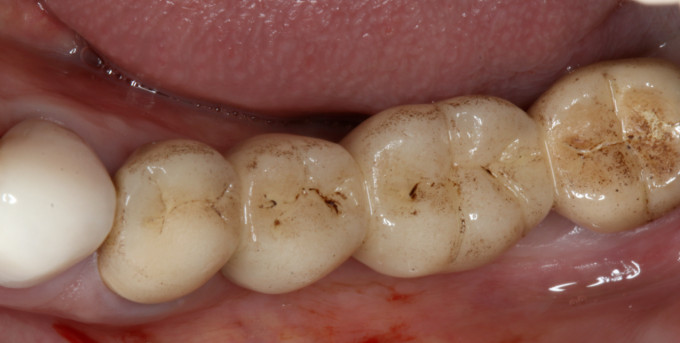
Image 2. Pre-op bridge

Image 3. Optical scan of pre-op bridge virtually extracting #19-21
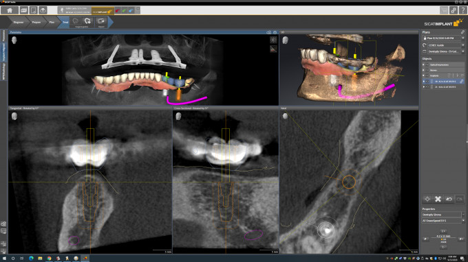
Image 4. Implant planning in SiCat 2.0 implant module

Image 5. Designed and milled surgical guide

Image 6. Bridge sectioned and removed

Image 7. CG3 surgical guide for position #19

Image 8. Guided ostetomy for implant #19

Image 9. IO FLO scan at time of surgery for custom healing abutments

Image 10. Completed surgery with stock healing abutments

Image 11. Atlantis designed custom healing abutments
The advantage of the custom healing abutments is to develop perfectly contoured tissue during the initial healing process. After the implants integrate, there is an option to alter the healing abutment design in order to create the final abutments using the same contours. This eliminates the need for imaging after healing. In this case, however, the decision was made to have the patient return for new imaging. At ten weeks post-surgery, the implants were imaged with IO FLOs for the final abutments. The file was sent to Dentsply Sirona Implants via the Connect 5.1 software. A prescription was filled out on Atlantis Weborder requesting parallel titanium abutments with concave emergence and tissue support for implants #19 and #21 (image 12). An insertion guide was also requested to ensure the abutments were placed in the correct position.

Image 12. Atlantis designed final abutments
A few hours later, the core file was ready. The model, with abutments #19 and #21 virtually placed, was imported into the CEREC Chairside 5.1 software (image 13). A three-unit zirconia bridge was designed and manufactured (image 14). On delivery, the custom healing abutments were removed, the final abutments were torqued into position with the aid of the insertion guide, and the zirconia bridge was cemented with RMGI cement (images 15-18). There was no need for anesthetic and almost no tissue blanching. Due to precise digital imaging of the gingiva with a Primescan, the final abutment contours were a perfect match of the custom healing abutment contours.

Image 13. Core file of virtually placed abutments
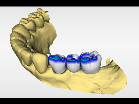
Image 14. Designed bridge #19-21 from core file

Image 15. Insertion guide with abutments and milled Zirconia bridge
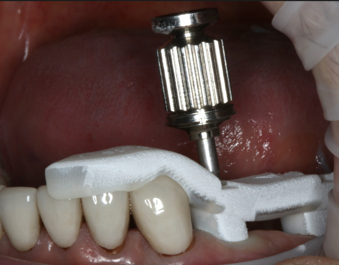
Image 16. Abutments seated and torqued with insertion guide
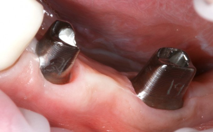
Image 17. Final titanium abutments #19 and #21

Image 18. Final cemented bridge #19-#21
The Atlantis workflow produced perfectly contoured and parallel titanium abutments, without having to fabricate the abutments chairside or bond them to a TiBase. As an added bonus, the core file that was included with the abutments allowed for the final bridge to be designed and fabricated without having to place or scan the abutments intraorally. The Atlantis workflow not only produces a precise fitting implant bridge, but it saves valuable time for both dentist and patient.